In my article Accelerate Onean Carver ride for heavy riders, I described how to speed up the Carver ride. One possibility is to use modified fins with additional wings. Here we will show you how to create such fins at home.
In the Part I we will show the basic solution with which I succeeded last year and the new solution (with practical rides not yet tested) with adjustable angles of attack and also a two-angle solution of wings with compression spring.
In the Part II, which I will finish at the end of this season, I will try to incorporate the best measured angles into the final solutions of wing fins with CNC metal connecting parts or bonded with carbon lamination.
Theoretical basis
First a little theory. As additional wings, we use side fins with an asymmetric foil (see Figure 1 - 1a), which have the underside flat. The center fin uses symmetric (true, 50/50) foil (see Figure 1 - 1b). The symmetrical foil has zero lift force at zero angle of attack (but drag force remains), the asymmetric foil has zero lift force at a slightly negative angle of attack. Due to the much higher density and incompressibility of water against air, the behavior of hydrofoiles is slightly different from airfoils, but the principle of creating lift force is the same.
Figure 1 - Foil theory
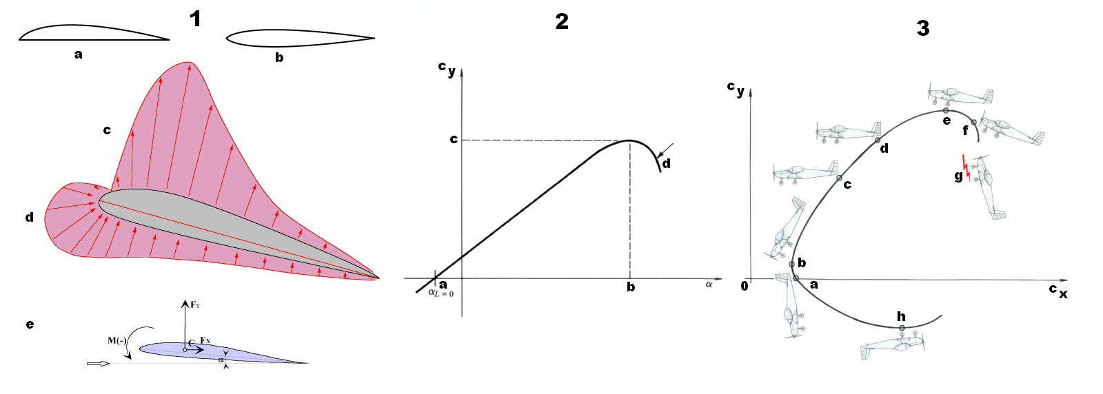
Figure 1 - 1c/1d Pressure profile around foil
c - pressure below free stream static pressure
d - pressure above free stream static pressure
Figure 1 - 1e Forces acting on the wing foil
Flow - airflow or hydroflow
C - gravity center
Fy (L) - lift force
Fx (D) - drag force
M(-) - negative pitching moment
α - angle of attack
The lift force has a static pressure and dynamic pressure component. Drag force is generated by friction and turbulence along the profile, but mainly behind the trailing (outlet) edge. Both forces depend on the angle of attack α (alpha).
Figure 1 - 2 Lift diagram
The lift diagram presents the coefficient of lift coefficient cy in relation to the angle of attack. The lift or drag coefficient is a dimensionless coefficient that relates the lift or drag force generated by a wing to the fluid density around the wing, the fluid velocity and an area of wing.
α - angle of attack
cy (cL) - lift coefficient
a - zero lift angle
b - angle for maximum lift (stalling angle of attack)
c - maximum lift coefficient
d - stall
Figure 1 - 3 Drag polar diagram of foil
The polar diagram presents the lift coefficient cy and the drag coefficient cx in relation to the angle of attack α. Each polar is valid for a Reynolds number. That is, for a certain speed range. The Reynolds number depends on the size of the wing, the speed and viscosity of the liquid. The size of the wing and the viscosity of the liquid are constant in our case, so only speed influences it. The tangent gives the maximum Fy/Fx or L/D (cy/cx (cL/cD)) point.
Interesting points on the polar diagram
a - zero lift (flight headlong)
b - steep descent (minimum drag)
c - greatest (best) glide (tangent led by the origin passing through)
d - least sinking (minimal sink rate)
e - maximum lift (for start and landing)
f - the lowest achievable speed (critical α)
g - stall due to flow separation
h - flight on back
We want to be on the curve of drag polar between the points of least drag, the slightest sinking and the highest gliding. So somewhere between points a to e. Ideally at point e at start and at point b at full speed.
Determination of the angle of attack
Determining the right angle of attack is very important. The small angle has little drag force but also less lift force. Big angle too much drag force. Surfboard also takes during ride a certain angle to the water surface (see Figure 2), which I estimated to be about 6°. Thus, for the wings themselves, the angle of attack is about 6° up to 12°, which I set approximately as the angle of maximum lift at reasonable drag.
Figure 2 - Surfboard angle of attack in combination with wings angle of attack to water surface
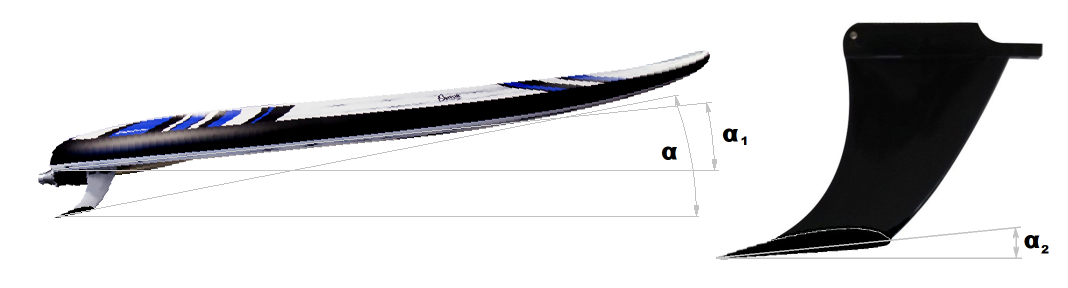
α - the angle of attack of the wings to the water surface
α1 - the angle of attack of the surfboard against the water surface
α2 - the angle of attack of the wings against the upper edge of the center fin
α = α1 + α2
Ideally, the angle of attack would be variable. When starting, higher, after reaching operating or at least planning speed as low as possible to reduce drag force. Theoretically, this could be achieved by controlling the wings with a bowden or servo, even the angle setting could be automatic depending on the speed actually measured. However, we will have to settle for a fixed angle of attack, possibly with a variable but preset constant angle of attack, at best with a two-position angle of attack - a higher starting angle, lower for full speed.
The moment of angle change is difficult to determine - it will only be determined by the compression spring(-s) hardness, which returns the angle of attack back to the starting position and the resultant of the lift and drag forces acting on the fin wings.
Last year I used a fixed angle of 6 ° for wings. I did only one measurement with a different angle of attack, with a 9° angle, at which I reached a maximum speed of 27 km/h. With an angle of 6 ° under the same conditions 30 km/h. Hence, a higher angle of attack is not more advantageous for my weight rider. However, it may be different for a heavier rider requiring higher lift force.
Therefore, in order to experiment with the angle of attack, I proposed a new way of attaching the wings to a central symmetrical fin allowing a change in the angle of attack in a certain range or even two positions of the angle of attack provided by the compression spring. In the first position with the higher angle of attack used for starting, in which the wings are pushed by the spring, the wings produce a higher lift, but also a higher drag. After reaching the speed at which the surfboard enters the planning, there is no need for such a high lift force and therefore a smaller angle of attack is sufficient. This will reduce the drag force and thus the surfboard can go faster. The angle is reduced automatically by compressing the spring by the lift force. However, it is problematic to determine the appropriate spring stiffness so that it is not compressed too early, ie before reaching the planning or too late or at all (too hard spring). This will be verified by experimental speed measurement using one or two compression springs.
Changing the fixed angle of attack or its range is done by inserting the insert into the hole in the central fin, through which the rear screw passes. The insert is an entire set of 0.5° for a range of 0° to 9°. The inserts can be very difficult to distinguish, so I designed a suitable box for them to be placed in the right place immediately after printing on a 3D printer.
Figure 3 - Inserts and box
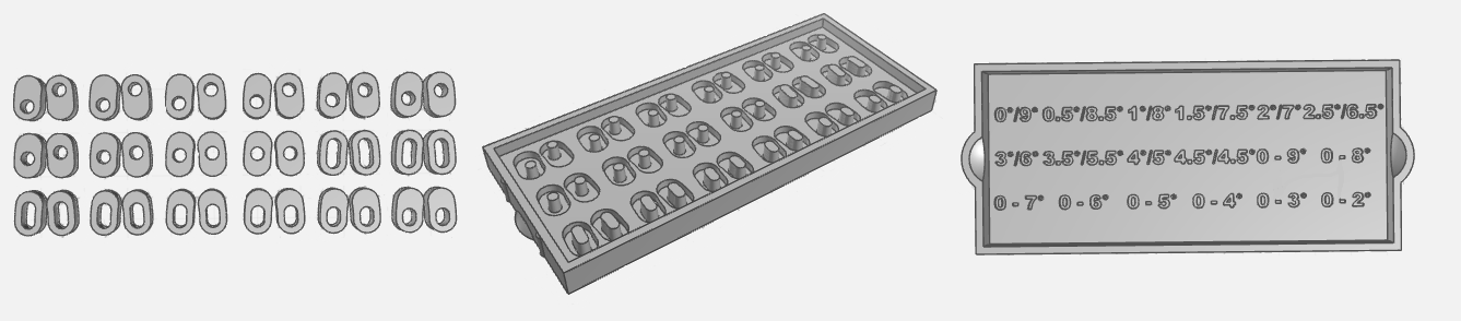
The models for Inserts and Box is available here. You can emphasize the printed numbers for better readability by filling the cavities with a different color material. I used white sanitary silicone for the black box.
Material and tools needed to make fins with wings
Figure 4 - Material for one winged fin
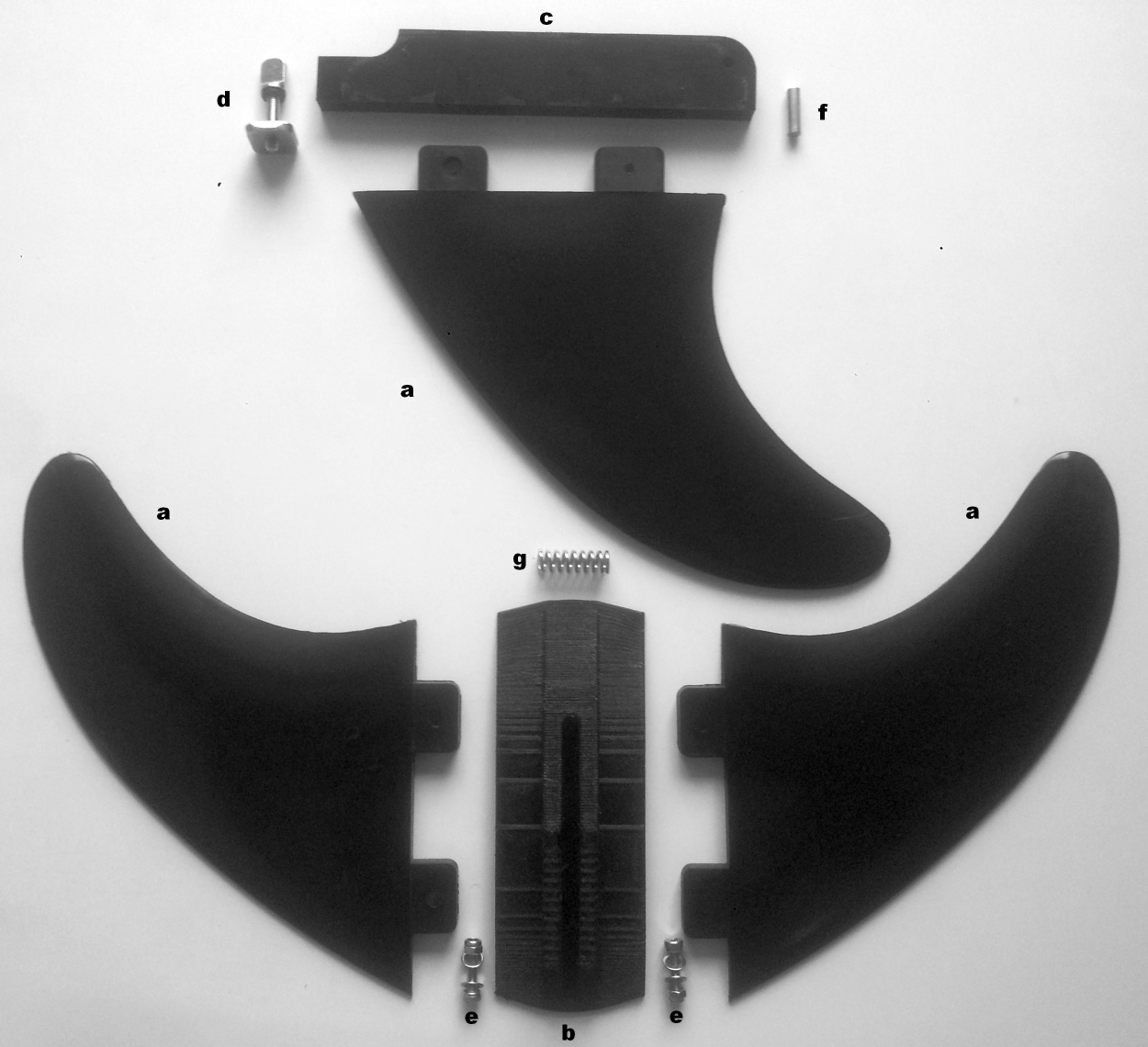
Material
- a - 2 sets of FCS G7 Tri Fins
- b - 2 pcs connecting part - wings holder (3D printing)
- c - 2 pcs finbox adapter (3D printing or purchased for central fins), can be replaced with 2 pcs of Single Center Longboard Fins or used more expensive Pacific Vibrations Fins (G7 or similar size) and then no need to solve finbox adapter
- d - 2 pcs no tool (manual) stainless steel fin screw for longboard
- e - 4 pcs stainless steel M3x12mm or M3x14mm Bolts with Nuts (plain or nylon self-locking) and washers (plain or internal or external toothed)
- f - 2 pcs center fin dowel pins 4x14 mm
- epoxy glue (bicomponent and waterproof)
Optional material
- g - spring 2-4 pcs (3D printer titan extruder strong spring Reprap MK8 I3)
- 3D printed inserts with box (see above)
Tools
- vice (preferably with rubber jaws)
- flat file, fine files (for finishing edges and holes)
- punch
- drill and drill bits with a diameter of 1 to 3mm or up to 6mm with using inserts
- screwdriver (M3 screw head type)
- brush for applying epoxy adhesive
Selection of fins set
As wings, the G7 or larger FSC fins are used. It is possible to use FCS Tri Fins or FCS Twin Fins + Center Single Fin (for example, Pacific Vibrations). It is also possible to use the original Onean Fins as Center Fins.
Figure 5 - Examples of suitable fins
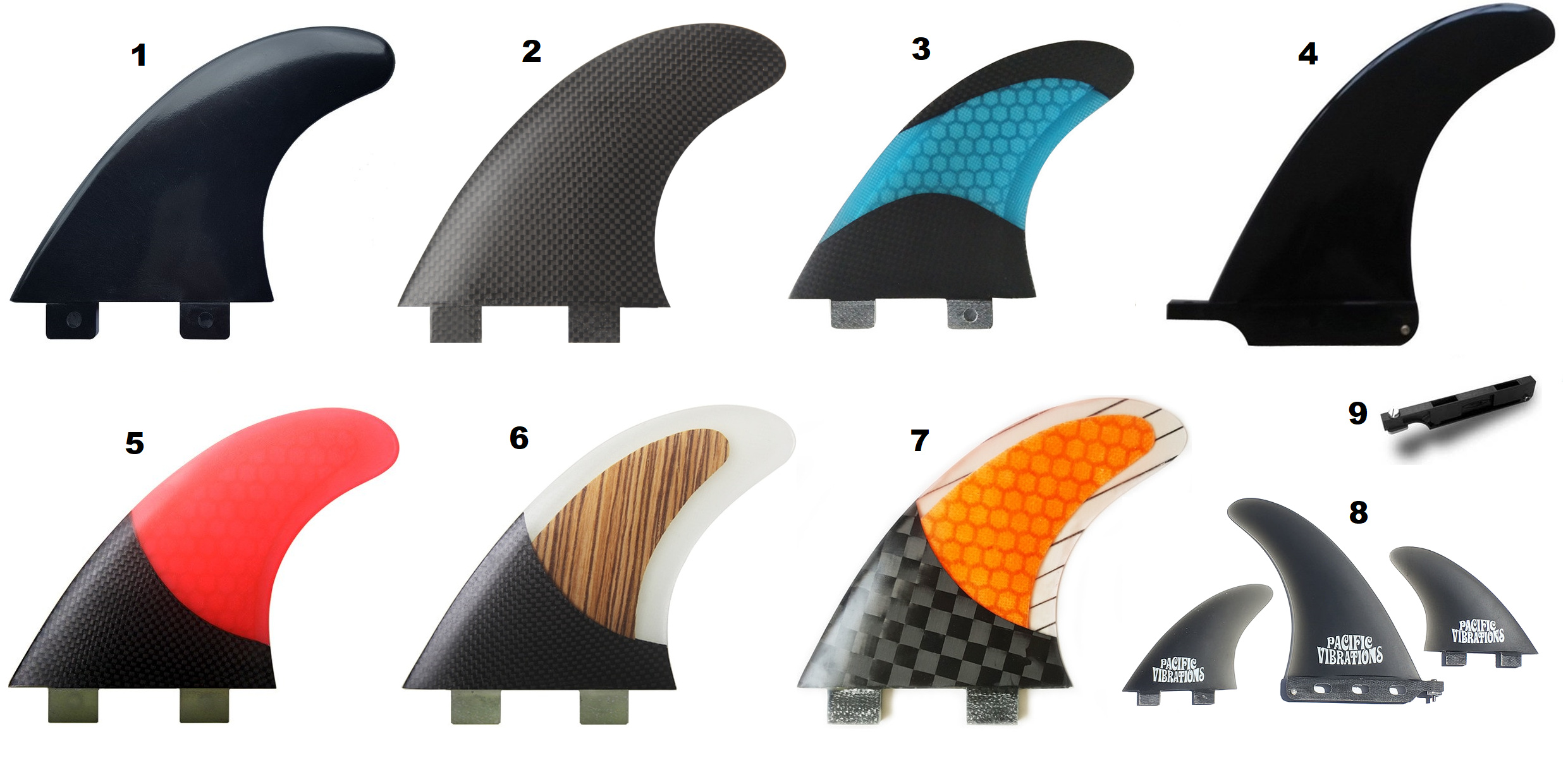
- 1 - FCS fins set G7 nylon ($23/2 sets)
- 2 - Carbon Black G7 ($70/2 sets)
- 3 - Carbon Blue G7 honeycomb ($61/2 sets)
- 4 - Center Longboard Fins 6.5" nylon (as a replacement for the FCS center fin + longboard adapter)($21/2 pcs)
- 5 - Red G7 honeycomb ($59/2 sets)
- 6 - Carbon Wood G7 ($59/2 sets)
- 7 - Carbon Orange G7 honeycomb $74/2 sets
- 8 - Pacific Vibrations 2+1 surfboard longboard 7" Center, 4.6" Sides FCS ($150/2 sets)
- 9 - FCS Longboard Box Adapter ($34/2 pcs)
Wings (side fins) holder selection
I offer to download 7 different models of G7 wings holder. All are downloadable from thingiverse.com.
Figure 6 - G7 side fins holder
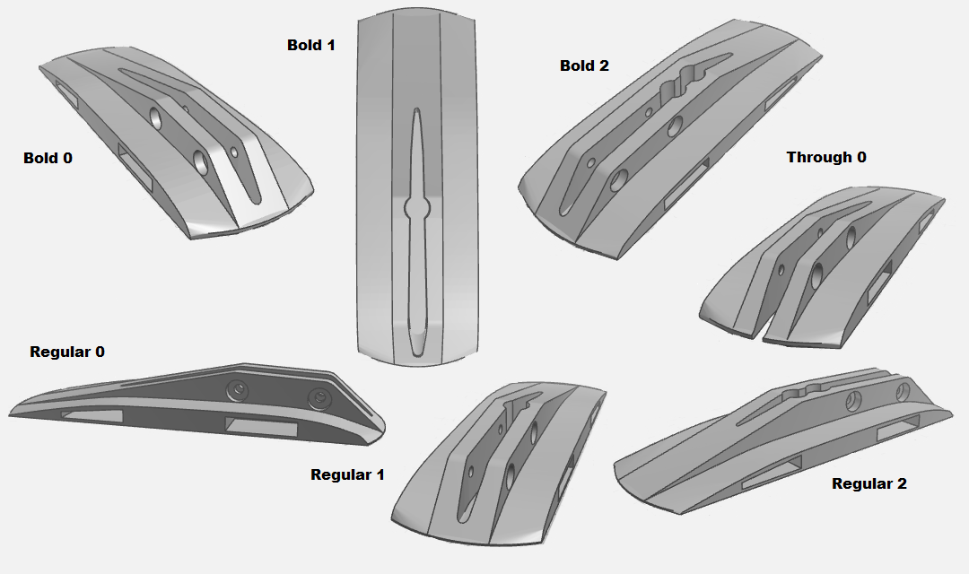
Regular versions are thinner and have less drag, but I only recommend them for SLS 3D printing (material Nylon 12 (Standard) or Carbon filled Nylon). SLS printing is more expensive but better (strength, accuracy). Bold versions are stronger and also suitable for 3D FDM printing. Recommended materials are PETG and Nylon. The numbers on the models indicate the number of holes for the springs. The Through 0 model requires no other modification of the center fin in addition to drilling holes for screws or for inserts.
If you do not own a 3D printer, you can print models using www.3dhubs.com. It offers many possibilities in both 3D printing and material selection. Ask for 100% infill for 3D printing. However, you may be asked for extra charge for material and longer print time.
Fin box adapter
Figure 7 - FCS to Longboard Fin box adapter

It is possible to use purchased FCS Longboard Box Adapter or Longboard Fin as Center Fin. You can also print the Finbox Adapter with this model on a 3D printer and simply stick it to the center fin with epoxy. There is a normal model and a high model that fills the surfboard groove at its full height. The box should be printed in its working position with touch build plate support.
Side fins modification
Side fins modification consists in reducing the thickness of the tabs exactly to the size of the G7 holder holes. Clamp the side fin into the vise and file with file to a new thickness of 4.4 mm front tab so that you remove the same thickness from both sides. File the rear tab to a thickness of 4.25mm evenly on both sides and then back side of the tab from the top to a thickness of 2mm.
Before starting filing, cover the fin surface near the tabs with adhesive tape to prevent scratches.
Figure 8 Side fins tabs modification
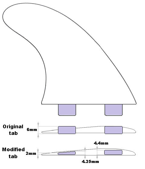
You don’t have to worry about weakening tabs. It has never cracked in this place before. The weakest point is the G7 holder. If you are trying to make sure that the tabs already adjusted fit into the holder holes, do not try it with more force. The holder walls are thin and easily cracked in those places.
Center fins modification
The modification of the center fin consists in filing the lower end of the fin under the selected angle αmin with a file and, if you use inserts or springs, you still have to file the front section at an angle αmax with a file.
Next, drill a hole (diameter 3.2mm) for the front screw. You can find the right place by using a punch through the front hole of the G7 holder, into which you will place the already filed center fin. The second hole is 25 mm from the first. You finish the Insert hole with the second hole created at the angle αmax - αmin. For Insert, this difference is always 9° and the hole diameter is 6.2mm. The recommended range for αmin is -2° to 3°, for αmax 7° to 12°.
Figure 9 Possible variations modifying of the center fin
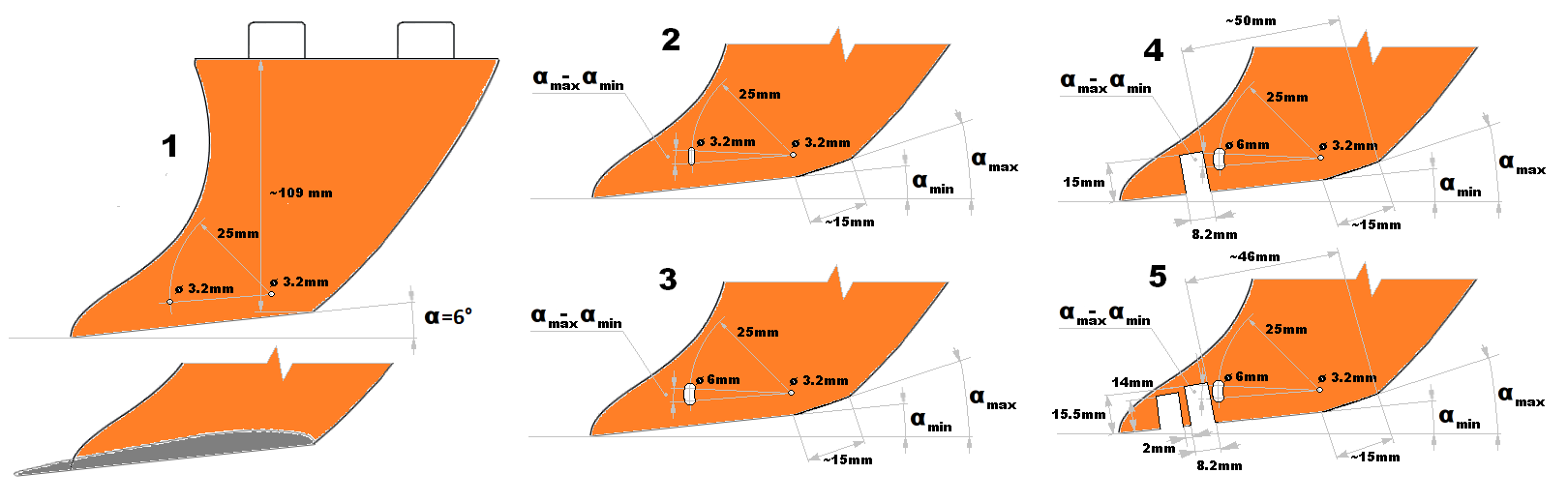
- 1 - corresponds exactly to the one I used last year, ie with a fixed angle of 6°. Any other angle in the range of -2° to 12° can be used. Inserts or springs are not used here.
- 2 - double angled variation without inserts (3.2mm holes) for use with 1 or 2 springs (as in variants 4 and 5). You can also use a larger range of angles αmin and αmax than just 9°.
- 3 - double angled variation with inserts (holes 6.2mm) without spring
- 4 - double angled variation with inserts (holes 6.2mm) with 1 spring
- 5 - double angled variation with inserts (holes 6.2mm) with 2 springs
When drilling holes eg for Insert at a radius of 25 mm, the distance between the hole centers for an angle of 9° is 3.923 mm.
Figure 10 Templates for the center fin
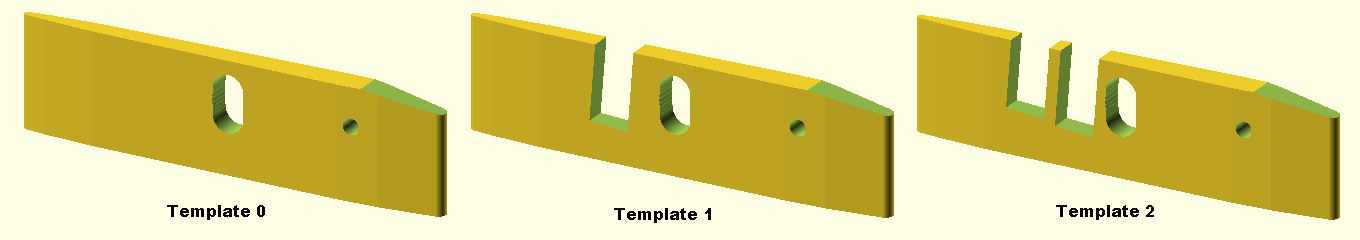
Models of three templates can be downloaded here. You can use the template to machine the underside of the center fin.
Template 0 is for Inserts without spring and αmax 9°. Template 1 is for one spring and Template 2 is for two springs.
Completing fins with wings
Glue dowel pins 4x14 mm into the Finbox adapter with epoxy. Do not force the pin into the hole, otherwise Finbox will break. Make the hole larger with a round file. I make pins from a screw shaft with a diameter of 4mm by sawing to a length of 14mm. Glue Finbox with the center fin with epoxy. Also cover the gap between the two parts with epoxy. Screw No tool fin screw into Finbox.
Glue the side fins into the G7 holder, apply the epoxy glue to the slots and holder surface, and smooth the surface with a soft sandpaper after drying. If necessary insert the insert and the spring (s) and screw the center fin with the G7 holder using M3 screws.
This is the work done. Enjoy a quick ride on Carver.
Trigger
Trigger for pressing the drop of wireless controller is a useful helper. Pressing the drop with only two fingers will get both fingers very tired soon. Trigger allows you to press on the drop of the entire palm.
Figure 11 Trigger
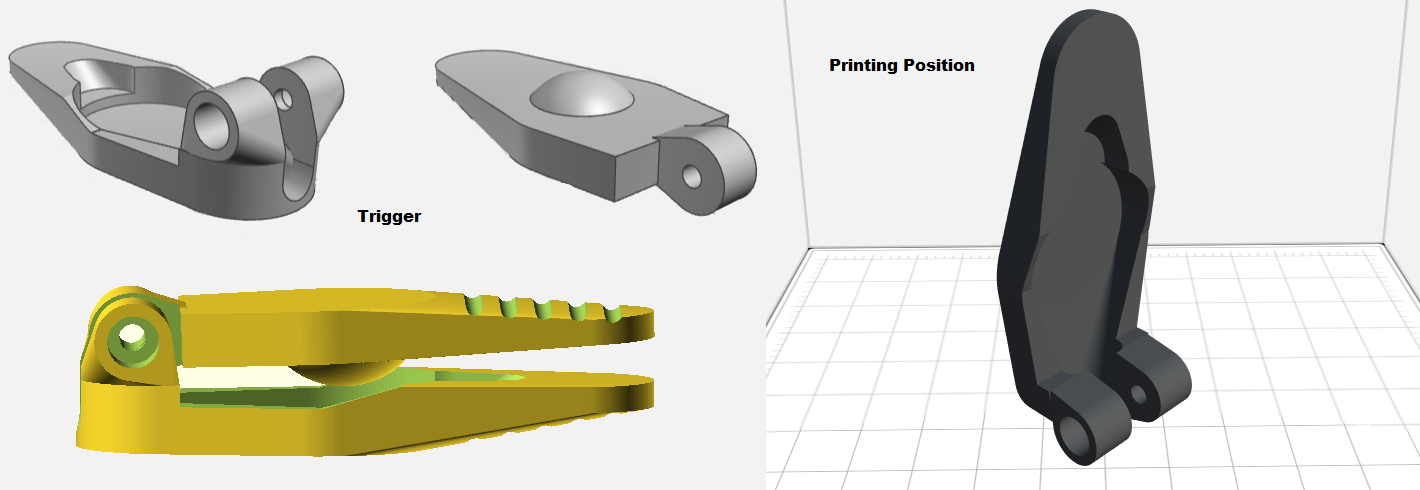
Material
- Trigger holder - printed in the height position with adhesion brim and touch build plate support
- Trigger button - printed in the height position with adhesion brim and touch build plate support
- (Hexagon) Screw M3x12+Nut M3
The Trigger model can be downloaded here.
To pair the surfboard with wireless controller, you need to pull the drop out of the bed by gently pushing the cord from the bottom and lifting the drop at the groove place at the top of the bed.
Printed parts need to be cleaned of burrs and sharp edges using fine files, especially at the point under the cable through which the cable passes.
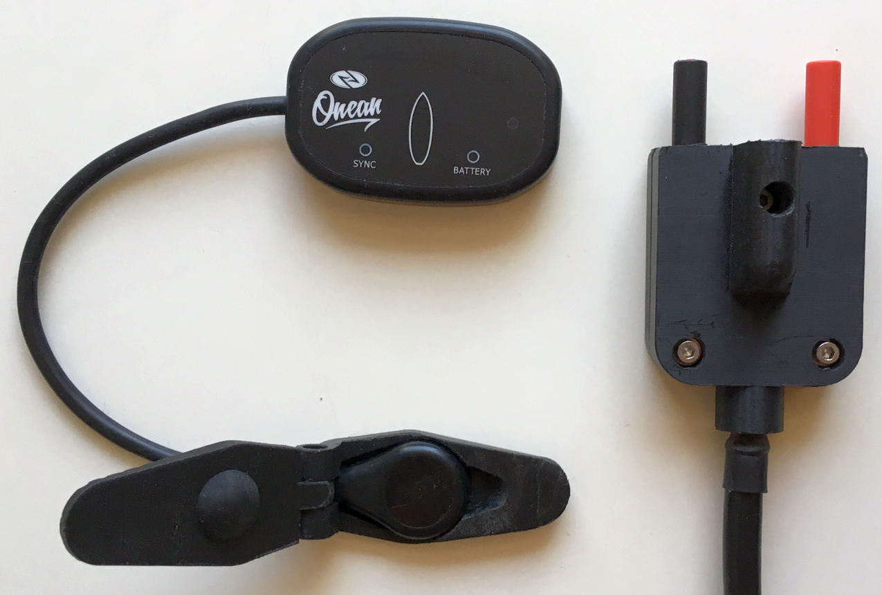
Battery Charger Connector
The original charging connector is very thin-walled, so it does not last much and, moreover, does not mechanically prevent insertion with reverse polarity. But it is equipped with a polarity reversal protection with a magnet. Without the magnet, charging will not start. Therefore, I designed a more robust connector design with a reverse polarity mechanical barrier and a built-in neodymium magnet required to start charging.
Figure 12 Battery Charger Connector
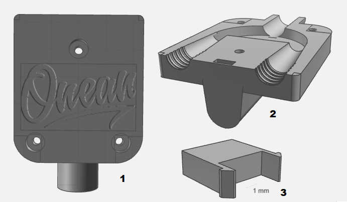
Material
- 1 - Connector top - printed in the height position with adhesion brim
- 2 - Connector bottom - printed in the height position with adhesion brim
- 3 - Connector magnet cap - very tiny model printed with adhesion brim
- (Hexagon) 3xScrew M3x8 + 3x Nut M3 + 6x Washer M3
- Neodymium magnet (diameter 5 mm, thickness 2 mm)
The Charger Connector model can be downloaded here.
The magnet is inserted into the slot at the front of the connector bottom and secured with a magnet cap once.
The correct polarity is very important for the connector assembly. The red pin must be on the left side when looking at the logo. Otherwise, the polarity is reversed, the magnet protection is not applied and the battery will be destroyed.
Figure 13 Trigger and Battery Charger Connector